

Which Aspect Of Your Drawing Is Due To Double Slit Interference And Which Is Due To Single Slit
Learning Objectives
Past the end of this department, you lot will be able to:
- Discuss the unmarried slit diffraction pattern.
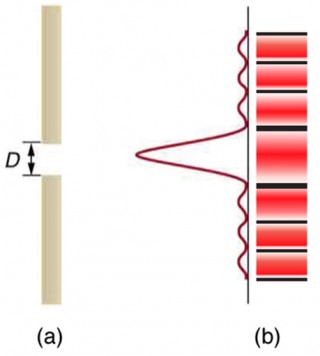
Effigy 1. (a) Single slit diffraction pattern. Monochromatic light passing through a single slit has a central maximum and many smaller and dimmer maxima on either side. The central maximum is six times higher than shown. (b) The drawing shows the bright central maximum and dimmer and thinner maxima on either side.
Light passing through a single slit forms a diffraction pattern somewhat dissimilar from those formed by double slits or diffraction gratings. Effigy 1 shows a unmarried slit diffraction design. Notation that the central maximum is larger than those on either side, and that the intensity decreases quickly on either side. In contrast, a diffraction grating produces evenly spaced lines that dim slowly on either side of center.
The analysis of single slit diffraction is illustrated in Effigy 2. Here nosotros consider light coming from unlike parts of the same slit. According to Huygens's principle, every part of the wavefront in the slit emits wavelets. These are like rays that start out in phase and head in all directions. (Each ray is perpendicular to the wavefront of a wavelet.) Assuming the screen is very far away compared with the size of the slit, rays heading toward a mutual destination are near parallel. When they travel straight alee, every bit in Effigy 2a, they remain in phase, and a central maximum is obtained. Even so, when rays travel at an angle θ relative to the original management of the beam, each travels a different distance to a common location, and they can get in in or out of stage. In Figure 2b, the ray from the bottom travels a altitude of one wavelength λ further than the ray from the summit. Thus a ray from the center travels a distance λ/2 further than the one on the left, arrives out of phase, and interferes destructively. A ray from slightly above the center and one from slightly above the bottom volition likewise cancel one another. In fact, each ray from the slit will have some other to interfere destructively, and a minimum in intensity volition occur at this angle. There will exist another minimum at the aforementioned angle to the right of the incident management of the light.
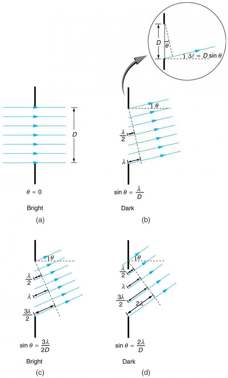
Figure two.
In Figure ii we see that light passing through a single slit is diffracted in all directions and may interfere constructively or destructively, depending on the angle. The difference in path length for rays from either side of the slit is seen to beD sinθ.
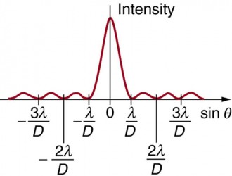
Figure iii. A graph of single slit diffraction intensity showing the central maximum to be wider and much more intense than those to the sides. In fact the central maximum is six times higher than shown here.
At the larger angle shown in Figure 2c, the path lengths differ past 3λ/2 for rays from the summit and bottom of the slit. One ray travels a altitude λ unlike from the ray from the bottom and arrives in phase, interfering constructively. Two rays, each from slightly to a higher place those two, volition also add together constructively. Near rays from the slit will have another to interfere with constructively, and a maximum in intensity will occur at this bending. Nonetheless, all rays do not interfere constructively for this situation, and and so the maximum is not every bit intense as the central maximum. Finally, in Figure 2d, the bending shown is big enough to produce a second minimum. Every bit seen in the figure, the difference in path length for rays from either side of the slit isD sinθ, and nosotros see that a destructive minimum is obtained when this distance is an integral multiple of the wavelength.
Thus, to obtain subversive interference for a single slit,D sinθ =mλ, form = 1,−i,two,−2,3, . . . (destructive), where D is the slit width, λ is the light'south wavelength, θ is the angle relative to the original management of the light, and g is the order of the minimum. Figure iii shows a graph of intensity for single slit interference, and it is apparent that the maxima on either side of the cardinal maximum are much less intense and not as wide. This is consistent with the illustration in Figure 1b.
Example 1. Calculating Single Slit Diffraction
Visible light of wavelength 550 nm falls on a single slit and produces its second diffraction minimum at an angle of 45.0º relative to the incident direction of the light.
- What is the width of the slit?
- At what angle is the offset minimum produced?
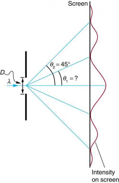
Figure 4.
A graph of the single slit diffraction design is analyzed in this example.
Strategy
From the given information, and assuming the screen is far abroad from the slit, we can use the equationD sinθ =mλ start to find D, and again to discover the angle for the first minimum θ 1.
Solution for Part one
We are given that λ= 550 nm, m= 2, and θ 2 = 45.0º. Solving the equation D sinθ =mλ for D and substituting known values gives
[latex]\begin{array}{lll}D&=&\frac{chiliad\lambda}{\sin\theta_2}=\frac{ii\left(550\text{ nm}\right)}{\sin45.0^{\circ}}\\\text{ }&=&\frac{1100\times10^{-9}}{0.707}\\\text{ }&=&1.56\times10^{-half-dozen}\end{assortment}\\[/latex]
Solution for Part 2
Solving the equationD sinθ =mλ for sinθ ane and substituting the known values gives
[latex]\displaystyle\sin\theta_1=\frac{m\lambda}{D}=\frac{1\left(550\times10^{-9}\text{ thou}\right)}{1.56\times10^{-6}\text{ m}}\\[/latex]
Thus the angle θ i isθ 1 = sin−one 0.354 = 20.7º.
Word
We run into that the slit is narrow (it is only a few times greater than the wavelength of light). This is consistent with the fact that calorie-free must interact with an object comparable in size to its wavelength in order to exhibit meaning wave furnishings such as this single slit diffraction pattern. We also come across that the central maximum extends 20.7º on either side of the original beam, for a width of about 41º. The bending betwixt the first and second minima is merely about 24º(45.0º − 20.7º). Thus the second maximum is only about one-half as broad every bit the central maximum.
Section Summary
- A single slit produces an interference blueprint characterized past a broad central maximum with narrower and dimmer maxima to the sides.
- In that location is subversive interference for a single slit when D sin θ = mλ, (grade = i,–1,2,–2,3, . . .), where D is the slit width, λ is the calorie-free'due south wavelength, θ is the angle relative to the original direction of the calorie-free, and chiliad is the order of the minimum. Note that there is no m = 0 minimum.
Conceptual Questions
- As the width of the slit producing a single-slit diffraction pattern is reduced, how will the diffraction pattern produced change?
Problems & Exercises
- (a) At what angle is the beginning minimum for 550-nm light falling on a unmarried slit of width ane.00 μm? (b) Will at that place be a second minimum?
- (a) Calculate the angle at which a 2.00-μm-wide slit produces its offset minimum for 410-nm violet lite. (b) Where is the beginning minimum for 700-nm red light?
- (a) How wide is a single slit that produces its showtime minimum for 633-nm light at an angle of 28.0º? (b) At what angle will the second minimum be?
- (a) What is the width of a single slit that produces its first minimum at lx.0º for 600-nm low-cal? (b) Find the wavelength of calorie-free that has its first minimum at 62.0º.
- Find the wavelength of light that has its tertiary minimum at an angle of 48.6º when it falls on a single slit of width 3.00 μm.
- Calculate the wavelength of light that produces its first minimum at an bending of 36.9º when falling on a single slit of width 1.00 μm.
- (a) Sodium vapor light averaging 589 nm in wavelength falls on a single slit of width 7.50 μm. At what angle does information technology produces its second minimum? (b) What is the highest-order minimum produced?
- (a) Discover the angle of the tertiary diffraction minimum for 633-nm calorie-free falling on a slit of width twenty.0 μm. (b) What slit width would place this minimum at 85.0º?
- (a) Notice the angle between the first minima for the two sodium vapor lines, which have wavelengths of 589.1 and 589.half-dozen nm, when they fall upon a single slit of width 2.00 μm. (b) What is the distance between these minima if the diffraction pattern falls on a screen 1.00 m from the slit? (c) Talk over the ease or difficulty of measuring such a distance.
- (a) What is the minimum width of a single slit (in multiples of λ) that will produce a first minimum for a wavelength λ? (b) What is its minimum width if it produces 50 minima? (c) 1000 minima?
- (a) If a single slit produces a beginning minimum at 14.5º, at what angle is the second-order minimum? (b) What is the angle of the third-order minimum? (c) Is there a fourth-order minimum? (d) Apply your answers to illustrate how the angular width of the central maximum is about twice the angular width of the side by side maximum (which is the angle between the outset and second minima).
- A double slit produces a diffraction design that is a combination of single and double slit interference. Find the ratio of the width of the slits to the separation betwixt them, if the commencement minimum of the single slit pattern falls on the 5th maximum of the double slit pattern. (This will greatly reduce the intensity of the 5th maximum.)
- Integrated Concepts. A water pause at the entrance to a harbor consists of a rock barrier with a 50.0-m-wide opening. Ocean waves of 20.0-k wavelength approach the opening straight on. At what bending to the incident direction are the boats inside the harbor most protected against wave action?
- Integrated Concepts. An shipping maintenance technician walks past a tall hangar door that acts similar a single slit for audio entering the hangar. Outside the door, on a line perpendicular to the opening in the door, a jet engine makes a 600-Hz audio. At what bending with the door will the technician observe the first minimum in audio intensity if the vertical opening is 0.800 m broad and the speed of audio is 340 m/s?
Glossary
destructive interference for a single slit:occurs when D sin θ = mλ, (form=1,–1,2,–2,iii, . . .), where D is the slit width, λ is the light'southward wavelength, θ is the angle relative to the original direction of the light, and m is the order of the minimum
Selected Solutions to Problems & Exercises
ane. (a) 33.4º; (b) No
three. (a) 1.35 × 10−six m; (b) 69.9º
5. 750 nm
seven. (a) 9.04º; (b) 12
ix. (a) 0.0150º; (b) 0.262 mm; (c) This distance is not hands measured by human heart, but under a microscope or magnifying drinking glass it is quite easily measurable.
eleven. (a) 30.1º; (b) 48.7º; (c) No; (d) 2θ 1 = (2)(14.5º) = 29º, θ 2 − θ one = xxx.05º − 14.5º = 15.56º. Thus, 29º ≈ (2)(15.56º) = 31.1º.
13. 23.6º and 53.1º

Source: https://courses.lumenlearning.com/austincc-physics2/chapter/27-5-single-slit-diffraction/
Posted by: johnsonequallown.blogspot.com
0 Response to "Which Aspect Of Your Drawing Is Due To Double Slit Interference And Which Is Due To Single Slit"
Post a Comment